Measuring signal strength on the RF12
27 June, 2013 - 16:31
I have a jeenode on top of the compost bin - the signal is very weak. So dug around and found someone was using the software rf12_getRSSI function to create a crude 7 level signal strength. I have got so far with my new found knowledge - able to get the following:
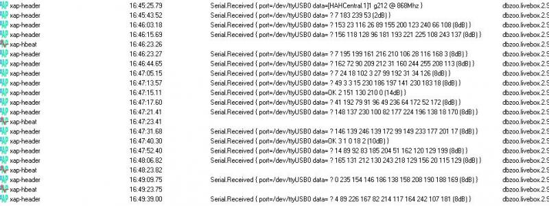
The data has been truncated from 20 to 10 items 'cos I am not really interested in all the junk.
Clearely the 8,10,14db is wrong - it is simply reporting the RSSI and not translating it - and this is where i have the problem.
First of all I take no credit for the idea - it is simply hacked from http://forum.jeelabs.net/node/1470.html
Without knowing how to use the version control properly or how to do patching I took the following approach:
1) I got a new version of RF12.cpp, RF12.h, RF12sio.cpp and RF12sio.h from https://github.com/jcw/jeelib/tree/rf12mods
(didn't know if I needed the last two files ) and simply poked them into the Arduino library (getting a red exclamation mark for my troubles)
2) Hacked the patch from the above forum link
for (byte i = 0; i < n; ++i) {
Serial.print(' ');
Serial.print((int) rf12_data[i]);
}
Serial.print(" (");
Serial.print(rf12_getRSSI(), DEC);
Serial.println("dB)");
into HAHcentral from
http://livebox-hah.googlecode.com/svn/trunk/userapps/arduino/HAHCentral/ which I believe is the
source for HAHCentral_nocfg.cpp.hex
3) It compiled much to my surprise and the result is above. I now use Arduino ERW 1.0.5 because that shows me where
the hex path is and I can upload the new sketch via the livebox without turning it all off.
The problem is that I would like to try and use the code from his patch which would seem to go into RF12.cpp
// return signal strength calculated out of DRSSI bit
+int8_t rf12_getRSSI() {
+    if (! drssi & B1000)
+        return 0;
+
+    const int8_t table[] = {-106, -100, -94, -88, -82, -76, -70};
+    return table[drssi & B111];
This will translate to a range from -70dB to -106 dB which is right.
I can't find out how to edit RF12.h without injecting loads of <CR><LF> which the compiler doesn't like. Arduino 1.0.3
won't edit this file type.
Any ideas? Will this approach work? I'm a bit worried about the B1000 stuff whatever that is!
I think having signal strength is useful to help diagnose difficult path tranmission cases - I can work with the 1 to 7 levels reported but would like to make it look right - who knows it may get incorporated and I can get rid of my exclamation marks.Regards
Kim
30 June, 2013 - 11:45
#3
Got it working
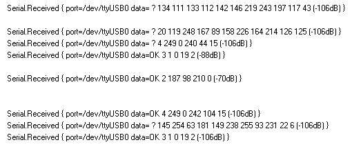
Now showing sensible crude signal strength.
You can see node 2 and 3 are quite strong. But node 4 is right down in at the same level as the noise.
Next I shall try making node 4 report more quickly - then I don't have to keep waiting approx 3 mins every
time I adjust the receiver position.
30 June, 2013 - 12:12
#4
very interesting work
I had always thought that the RSSI piece on these modules needed some external analogue components in order to work. This piece is really interesting. It would be good to know if doubling the antenna length on the remote Node made a worthwhile difference.
A 'setup' version of the code could assist with the optimal positioning of the Nodes.
All good stuff.
I've been a little busy elsewhere lately and to tell the truth not really read your post in any depth but the & B1000 is just 'ANDing' with drssi with binary value 1000 i.e. it is checking to see if bit 3 is on (assuming you count from bit 0)
To remove the <cr><lf> (and any other supious control bytes) run dos2unix on the file
e.g. if the file is example.txt then type dos2unix example.txt from the command prompt on the HAH